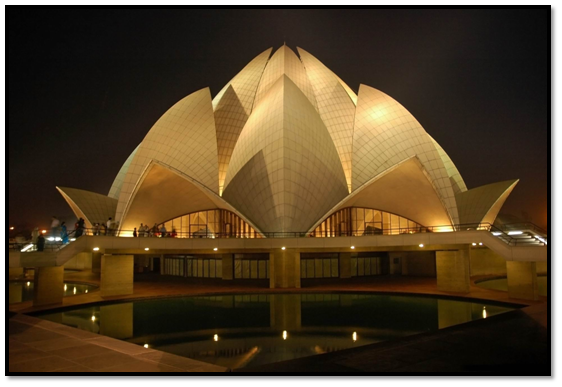
The temple gives the impression of a half-open lotus flower, afloat, surrounded by its leaves. Each component of the temple is repeated nine times.
The temple complex, as seen from the layout, consists of the main house of worship; the ancillary block which houses the reception center, the library and the administrative building; and the restrooms block.
The temple proper comprises a basement to accommodate the electrical and plumbing components, and a lotus-shaped superstructure to house the assembly area.
All around the lotus are walkways with beautiful curved balustrades, bridges and stairs, which surround the nine pools representing the floating leaves of the
lotus. Apart from serving an obvious aesthetic function, the pools also help ventilate the building.
The lotus, as seen from outside, has three sets of leaves or petals, all of which are made out of thin concrete shells. The outermost set of nine petals, called the 'entrance leaves', open outwards and form the nine entrances all around the outer annular hall. The next set of nine petals, called the 'outer leaves', point inwards.
The entrance and outer leaves together cover the outer hall. The third set of nine petals, called the 'inner leaves’ appear to be partly closed. Only the tips open out,
somewhat like a partly opened bud. This portion, which rises above the rest, forms the main structure housing the central hall. Near the top where the leaves separate out nine radial beams provide the necessary lateral support.
Since the lotus is open at the top, a glass and steel roof at the level of the radial beams provides protection from rain and facilitates the entry of natural light into the auditorium. Below the entrance leaves and outer leaves, nine massive arches rise in a ring. A row of steps through each arch lead into the main hall.
The inner leaves enclose the interior dome in a canopy made of crisscrossing ribs and shells of intricate pattern. When viewed from inside, each layer of ribs and
shells disappear as it rises, behind the next, lower layer.
Some of the ribs converge radially and meet at a central hub. The radial beams emanating from the inner leaves described earlier meet at the centre of the building and rest on this hub. A neoprene pad is provided between the radial beams and the top of the interior dome to allow lateral movement caused by the effects of temperature changes and wind.
GEOMETRY
The beautiful concept of the lotus, as conceived by the architect, had to be converted into definable geometrical shapes such as spheres, cylinders, toroids and cones.
These shapes were translated into equations, which were then used as a basis for structural analysis and engineering drawings. The resultant geometry was so complex that it took the designers over two and a half years to complete the detailed drawings of the temple.
Entrance leaves and outer leaves
The shell surfaces on both sides of the ridge of the entrance and outer leaves are formed out of spheres of different radii, with their centres located at different points inside the building.
There is one set of spheres for the entrance leaves, some of which define the inner surfaces and others which define the outer surfaces of
the shells. The diameters of the spheres have been fixed to satisfy the structural consideration of varying shell thickness.
Similarly, for the outer leaves, another set of spheres defines the inner and outer surfaces of the shells.
However, for the outer leaves, the shell is uniformly 133 mm thick towards the bottom, and increases to 255 mm up to the tip, beyond the glazing line.
The entrance leaf is 18.2m wide at the entrance and rises 7.8m above the podium level.
The outer leaf is 15.4m wide and rises up to 22.5m above the podium.
Inner leaves
Each corrugation of the inner leaf, comprising a cusp (ridge) and a re-entrant (valley), is made up of two toroidal surfaces. A toroid is generated when a circle of
a certain radius, ‘r, is rotated around the centre of a circle of much larger radius, 'R: A cycle tube is a typical toroid. The shaded portion of the toroid is a part of the
inner leaf shell.
The inner leaves rise to an elevation of 34.3m above the inner podium. At the lowest level each shell has a maximum width of 14m. It is uniformly 200mm thick.
Arch
All around the central hall are nine splendid arches placed at angular intervals of 40 degrees. The shape of these arches is formed by a number of plane, conical and
cylindrical surfaces. The intersection of these surfaces provides interesting contours and greatly enhances the beauty of the arches. The nine arches bear almost the entire load of the superstructure.
Interior dome
Three ribs spring from the crown of each arch. While the central one (the dome rib) rises radially towards the central hub, the other two (the base ribs) move away from the central rib and intersect with similar base ribs of adjacent arches, thus forming an intricate pattern. Other radial ribs rise from each of these intersections and
all meet at the centre of the dome.
Up to a certain height, the space between the ribs is covered by two layers of 60mm-thick shells.
SETTING OUT
Unlike conventional structures for which the elements are defined by dimensions and levels, here the shape, size, thickness, and other details were indicated in the drawings only by levels, radii, and equations.
These parameters, therefore, had to be converted into a set of dimensions in terms of length, breadth, height, and thickness, easily understood by a site engineer or a carpentry foreman.
To achieve this, a system of coordinates along x, y and z axes for every 40 degrees. Segment of the temple was worked out with the help of a computer. The problem was then further simplified by working out from these co-ordinates levels and distances which a carpenter or a reinforcement fitter could easily comprehend and then arrive at the surfaces and boundaries.
Eighteen reference stations were established outside the building for setting out the arches, entrance, outer and inner leaves.
First, 18 radial lines were established from the centre of the building. Along these lines, using inclined and vertical distances, end points A and B for surface (1) were established. By using a set of curved templates, each of varying curvature, surface (1) between these lines was developed. From this surface the other surfaces of the arch were set out by using stepped templates with respect to surface (1).
The stations were used to set out the cusp, re-entrance and edge lines for the entrance, outer and inner leaves. For example, to arrive at curve AB point A with coordinates XA, YA, ZA was defined with respect to 0. AB was then established by a second theodolite and the curve AB determined by a stepped template. Accurately made curved templates of required radii were then used to develop the surface between these boundaries.
SEQUENCES OF CONSTRUCTION
The basement and the inner podium were constructed first. Thereafter, for casting the arches and shells, the structure was divided into convenient parts, taking into
consideration that when deshuttered, the portion of the shells cast would be self-supporting until the remaining shells were completed. The structure was divided as
follows:
Arch
All 9 arches were cast one after the other in two lifts until the circle was completed. The deshuttering of the soffit of each arch was taken up after the adjacent arches
had attained specified strength.
Inner leaf, radial beams and central hub
After the completion of all the arches, the structural steel staging for the inner leaf was erected. Three shells, 120 deg. apart, were taken up at a time and cast in two
lifts, one after the other, up to the radial beam level, ensuring always that the difference in height between the shells cast was not more than one lift.
The process was repeated until all 9 segments were cast. Casting of the central hub was taken up as an independent activity, and after all the shells were cast, they were connected to the hub by casting the radial beams. After sufficient curing, the inner leaf along with the radial beams were dewedged, leaving the central hub supported. The remaining portion of the inner leaf was then taken up.
Interior dome
After de-wedging of inner leaf, the steel staging was modified and two folds of shells of the interior dome taken up one after another. For each fold, three shells, 120 deg. apart, were taken up at a time and cast one after another. For each shell the boundary ribs were taken up first and then the shell cast in one single lift. The process was repeated until all the shells were completed.
Entrance and outer leaves
The construction of the entrance and outer leaves was taken up as a parallel activity with the casting of the inner leaves and interior dome. Two entrance leaves and one intermediate outer leaf were taken up first. Thereafter, the outer and entrance leaves were cast alternately, the outer leaf first and then the adjacent entrance leaves. Deshuttering was started with a pair of outer leaves and followed by the intermediate entrance leaf. In this manner the remaining leaves were deshuttered as and when the concrete attained strength and the leaves adjacent to the shell to be deshuttered were cast.
STAGING AND FORMWORK
Deflection was an important consideration in the design of the formwork. The maximum deflection was limited to 3mm over a distance of 1m (including errors in
fabrication and erection).
The following aspects were considered in arriving at the general arrangement of the staging supporting the Inner leaf and interior dome formwork:
1. The concreting of the shells should be taken up 3 at a time, 120 deg, apart, so that the lateral loads on the staging supporting the formwork were reduced as far as possible.
2. Construction joints were to be avoided as far as possible so that the exposed concrete surface did not show any lines other than the architectural pattern. For the inner leaf, construction joints were to be located above 24.8m level so that they did not show from the floor level. All other shells were to be cast in a single continuous pour.
3. The staging should support the radial and base ribs without interfering with the structural steel members. After deshuttering of inner leaf, the structure should be able to support the formwork of the inner layers of shells of the interior dome with minimum modification.
From the above considerations, a space frame consisting of 9 radial cusp frames and 9 re-entrant frames, with circumferential and diagonal members closely following the profile of ribs and shells, was considered most suitable.

Various alternatives were considered for the steel staging. Standard pipe scaffolding was found to be unsuitable, considering that the slippage of members at joints would be uncertain and it would be difficult to compute and control the deflection, particularly due to lateral loads. Structural steel framework with bolted joints was found to be unsatisfactory, considering that a very high degree of accuracy in fabrication and erection of structural work would be required to match the bolt holes at junctions of members meeting at different inclinations in all three planes. Structural steel framework with welded joints was considered to be most suitable because deflections due to slippage of joints would be avoided and fabrication and erection would be comparatively easier.
The inner surfaces of all the shells have a uniform, bush-hammered, exposed concrete surface with architectural patterns. For the inner leaves, these patterns were formed out of radial and vertical planes intersecting the surface of the torus. For the outer and entrance leaves and the interior dome, the patterns were formed out of longitudes and latitudes of spheres. The formwork was designed in a manner that timber joists support the panels instead of the regular pattern of the structural steel supporting members of the space frame.
Full-scale mockups of the bottom surface of each of the shells were first made at ground level and the architectural patterns marked on this surface. The frame of each form panel was fabricated according to calculated dimensions and cross-checked with measurements from the mockup.
The inner formwork for every petal was fully fixed from bottom to top and aligned accurately. After the formwork was approved, the sheathing joints where sealed with putty made out of epoxy resin and plaster of Paris and a protective coating was applied over the plywood surface. In the case of the interior dome shells, the plywood sheathing was lined by fiber-reinforced plastic sheets and the joints sealed with epoxy resin. After this, the location of each reinforcement bar was marked on the formwork along latitudes and longitudes and the bans placed over the markings. To avoid impressions of cold joints on the inner surface, the casting of petals of the inner leaf was carried out in three lifts, some of them 14m high. To facilitate placement of concrete and simultaneous compaction in each pour, the outer formwork was placed one row of panels at a time, and as the level of concrete rose, the next row of panels was fixed. These panels therefore, had to be fixed in position and aligned accurately In the shortest possible time.

Through selected points matching with the architectural pattern, pipe supports were taken from the inner leaf staging. These pipes supported a structural steel grid closely following the profile of the outer surface of the shells. The grid supported the outer formwork against the concrete pressure and also accommodated the working platforms at all levels. Through-ties connecting the inner and outer forms were provided at selected points so as to reduce the load on the steel staging and limit the deflection of formwork.
The longitudinal support members of the backform had accurately aligned shaped members, such that when the backform panels were placed in position and wedged, the outer surface of the shell was attained without further alignment. To ensure that the panels fitted exactly between the shaped members and there was no delay, the fixing of the panels for the entire shell was carried out in advance.
LOADING
The following loads were considered for the design of the
formwork:
1. Dead load of formwork- 750 N/m2 of surface area.
2. Self-weight of structural steel members.
3. Live load 2000 N/m2 of plan area.
4. The greater of dead load of concrete (or) liquid pressure at any point corresponding to the rate of placement 0.45 m/hr and minimum temperature of 10 deg. C (during winter).
Liquid pressure p = 7.2 + ([785R]/[Tc + 17.8))
P Lateral liquid pressure - KN/m2
R = Rate of placement-m/hr
Tc= Temperature of concrete in the forms deg. C
5. Basic wind pressure = 1000 N/m2
For the inner leaf, various combinations of the above loads were considered for the following conditions:
Stage I Concrete from top of arch to +24.8m level
Stage II Concrete from +24.8m to +38m level
Stage III Concrete from +38.8m to the top
The combination of loads considered were:
1. Self-weight of space frame (symmetrical)
2. Dead load of shutter
3. Live load + dead load of concrete Stage I (unsymmetrical)
4. Live load + dead load of concrete Stage I (symmetrical)
5. Live load+ dead load of concrete Stage II (unsymmetrical)
6. Live load + dead load of concrete Stage II (symmetrical)
7. Live load+ dead load of concrete Stage III (unsymmetrical)
8. Live load + dead load of concrete Stage III (symmetrical)
9. Wind load for full height (unsymmetrical)
Based on the above loads, a computer analysis for all possible combinations was carried out using SAP IV program. One cusp frame and one re-entrant frame along with inter-connecting bracings were considered as a unit.
Similar loading conditions were considered for the entrance and outer leaves as also the shells of the interior dome, the only difference being that all shells were cast in a single pour.
REINFORCEMENT
The reinforcement used in the white concrete shells as well as the binding wires was entirely galvanized so as to prevent the long-term effect of rusting of reinforcement on the white concrete. Since galvanized reinforcement for concrete is seldom used in this country, several tests were carried out to ensure that the mechanical properties of reinforcement did not become adversely affected due to galvanizing. Sandblasting was carried out to reduce pickling time with a view to avoiding hydrogen embrittlement. The bottom formwork for one shell for each of the leaves was first erected and aligned. The edge lines and surfaces of this formwork were then used as a mockup to decide the length and shape of each bar in the shell. To avoid the impression of cover blocks on the exposed surface of the shells, the inner layer of reinforcement was held in position by special steel spacers supported from the outer formwork.
CONCRETE
All the ribs and shells up to radial beam level are in white concrete. To avoid crazing and shrinkage cracks, a mix of M 30 grade white concrete was designed considering that the cement content should be below 500 kg/m3 and the quantity of water reduced to a minimum.
Tests carried out on Indian cement revealed that the strength and other properties varied considerably and the colour did not meet the architectural requirement. Trial mixes also showed a higher cement requirement of 430-450 kg/m3. The entire quantity of white cement was therefore imported from Korea. With the imported se
cement, it was possible to produce concrete having 28 days cube strength of 55-60 N/mm2 with a cement content of 380 to 400 Kg/m3. A mix of 1:1.44:3.36 and w/c ratio of 42 was adopted. To achieve a high workability, slump 1-120 mm, super plasticiser, 5 to .75% by weight of cement was used.
Specially graded dolomite aggregates were procured from the Alwar mines near Delhi and white silica sand from Jaipur. The maximum temperature of concrete at
the time of placing was limited to 30 deg. C. During the summer months, when the ambient temperature was as high as 45 deg. C, the temperature of the concrete was
controlled by adding a measured quantity of ice and by the precooling of aggregates in air-cooled aggregate storage bins. To avoid cold joints due to stoppage of work during heavy rains, as also to protect rain water entering the forms, the entire concreting area was covered by tarpaulins.
After removal of the outer forms, the surface of the concrete was covered with hessian and cured for 28 days by keeping it wet continuously by a sprinkler arrangement fixed at the top of the shells.
MARBLE CLADDING
The outer surface of the shells, as also the inner surface of the arches, are cladded with white marble panels fixed to the concrete surface with specially designed stainless steel brackets and anchors. 10,000 sq.m. of marble was quarried from the Mount Pentilekon mines of Greece and thereafter sent to Italy, where each panel was cut to the required size and shape to suit the geometry and architectural pattern before transporting them to the site in Delhi.
After waterproofing of the top surface of each shell, Timber templates of the same size as the marble panels were used to define the location of the bottom-most rows of marble panels first. The geometry of the cusp re-entrant and edge lines was then accurately checked with respect to these panels and the marble pieces were fixed in position from bottom towards top and cusp towards re-entrants and edges. Edge holes were drilled at ground level for each marble panel before the panels were placed in position. Holes were drilled in the concrete to accommodate the anchor fasteners of the stainless steel brackets to suit the holes in the marble, after each panel was aligned. After fixing of the brackets, the area around the bracket hole was sealed with a special waterproofing compound.


The alignment of the panels was adjusted at each layer so that the surface geometry and pattern lines were maintained. The pieces near edge, re-entrant and cusp lines were cut to suit the boundary lines. Gaps B to 10 mm wide at the joints were filled with moulded rubber cordon, and the top of the joints, as also the holes in the marble, sealed with silicon sealant. The entire marble surface was, lastly, washed with a solution of 30% muriartic acid mixed in water, to remove dirt and stains.
A specially designed structural steel framework was provided to accommodate access and working platforms. The platforms were free from the surface of the shells so that the marble fixing could be carried out without any hindrance from the supports of the staging.
NATURAL LIGHTING
• The whole superstructure is designed to function as a skylight. The interior dome is spherical and patterned after the innermost portion of the lotus flower.
• Light enters the hall in the same way as it passes through the inner folds of the lotus petals. The interior dome, therefore, is like a bud consisting of 27 petals, and light filters through these inner folds and is diffused throughout the hall.
• The central bud is held by nine open petals, each of which functions as a skylight. The nine entrance petals complete the design.
ART
With the rise of religious art in India, the lotus appeared on all the Buddhist monuments which came into being in different parts of the country from about 200 B.C. onwards. In its simplest form, the expanded lotus appears frequently as a circular ornament in the sculptures at Sanchi, Bharhut, Amravati, and Bodh Gaya, as well as in the rock-cut Buddhist temples of Western India, introduced as medallions on pillars, panels, and ceilings. Elaborately carved half-lotuses sometimes appear in these settings, or, in Sri Lanka, as so-called-moon-stones on semi-circular
stone slabs at the foot of staircases. Lotuses growing on stems also occur in the sculptures of Gandhara and of Mathura, and often figure in elaborate floral designs on the pillars of Sanchi or the panels of Amravati.
Further, from earliest times, the lotus is fashioned either as a seat or as a pedestal on which divine or sacred beings rest in a sitting or standing posture. The oldest and most striking example of this use is exhibited in the figure of the Hindu goddess Lakshmi, in the Buddhist sculptures at Udayagiri, at Bharhut, and especially at Sanchi, where it is frequently repeated on the gateways of the Great Stupa. Lakshmi is portrayed sitting or standing on a lotus and holding a lotus flower in each hand watered by two pots raised aloft by the trunks of two elephants. This ancient motif is found all over India to the present day and occurs as well among the old sculptures at Polonaruwa in Sn Lanka.
The lotus symbol can be easily traced in Zotoastrian architecture. The carving of Ardashir lI at Taq-i-Bustan shows Mithra, standing on a lotus flower. In the bas-relief at Persepolis the king and most of his nobles each hold a lotus in their hands The lotus is one of the oldest and most beautful elements in the patterns of Persian carpets, and it can often be seen in Islamic architecture. For example, the shape of a lotus occurs in the design of the perforated plaster work in the mihrab (prayer niche) of the Malik mosque in Kirman.
Thus it shows how the lotus has been used as a unifying symbol in all the Indian religions.
In the design of the Baha'i House of Worship, however, the symbol has been employed in an unprecedented fashion. The most basic idea in the design is that light and water are used as its two fundamental elements, and that these two elements alone are responsible for the ornamentation of the House of Worship in place of the thousands of statues and carvings to be found in other temples.
Click
here to read similar posts
Click
here to see my substandard artwork 🙈


Insightful article you have here. I did a write up myself on this subject some time ago, and I wish I had your brief article as a resource back then. Oh well. Thanks again for this report
ReplyDeleteAvira Antivirus Pro Crack
Driver Talent Pro Crack
Bitwig Studio Crack
Sketch Crack
TeamViewer Crack
Sorry for the late response and Thanks a lot!!!
Delete